|
Most of the site will reflect the ongoing surgical activity of Prof. Munir Elias MD., PhD. with brief slides and weekly activity.
Functional Neurosurgery
functionalneuro.surgery
Functionalneurosurgery.net
IOM Sites
iomonitoring.org
operativemonitoring.com
Neurosurgical Sites
neurosurgery.art
neurosurgery.me
neurosurgery.mx
skullbase.surgery
Neurosurgical Encyclopedia
neurosurgicalencyclopedia.org
Neurooncological Sites
acousticschwannoma.com
craniopharyngiomas.com
ependymomas.com
gliomas.info
gliomas.uk
meningiomas.org
neurooncology.me
pinealomas.com
pituitaryadenomas.com
Neuroanatomical Sites
humanneuroanatomy.com
microneuroanatomy.com
Neuroanesthesia Sites
neuro-anesthessia.org
Neurobiological Sites
humanneurobiology.com
Neurohistopathological
neurorhistopathology.com
Neuro ICU Site
neuroicu.info
Neuroophthalmological
neuroophthalmology.org
Neurophysiological Sites
humanneurophysiology.com
Neuroradiological Sites
neuroradiology.today
NeuroSience Sites
neuro.science
Neurovascular Sites
vascularneurosurgery.com
Personal Sites
cns.clinic
Spine Surgery Sites
spine.surgery
spondylolisthesis.info
paraplegia.today
Stem Cell Therapy Site
neurostemcell.com
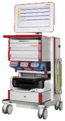
Inomed Stockert Neuro N50. A versatile
RF lesion generator and stimulator for
countless applications and many uses
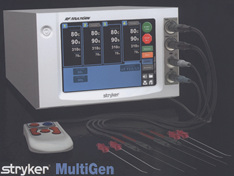
Multigen RF lesion generator .
|
|
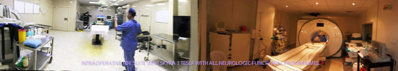
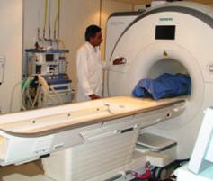 Skyra MRI with all clinical applications in the run since 28-Novemeber-2013.
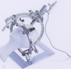
Inomed Riechert-Mundinger System, with three point
fixation is the most accurate system in the market. The microdrive and
its sensor gives feed back about the localization.
Inomed MER system
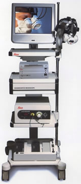
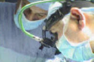
Leica HM500
The World's first and the only Headmounted Microscope.
Freedom combined with Outstanding Vision, but very bad video recording and
documentation.
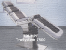
After long years TRUMPF TruSystem 7500 is running with in the neurosuite at
Shmaisani hospital starting from 23-March-2014
|